
Building an RGB LED Circuit#
In this section, you will build a circuit that blinks red, green, and blue on the RGB LED. The wire colors match the color of the LED in this circuit to help visually. If the wire colors are not available, the circuit will still work.
Attach the micro:bit to the Kitronik prototyping plate in the edge connector. Be sure that the micro:bit is inserted with the LED display facing up all the way in the edge connector, and not at an angle.

Insert the RGB LED in the breadboard. The LED in the kit is a common cathode RGB LED as in the diagram displayed below:

Take note of where the longer lead is, as this is the ground. Place the RGB LED in the breadboard.

Take a 47Ω resistor and place one lead in the same row as the red lead on the RGB LED and the other lead a few rows away from it.

Take another 47Ω resistor. Place one lead in the same row as the green lead, and the other lead a few rows away from it as you did with the red lead on the RGB LED.
Take another 47Ω resistor. Place one lead in the same row as the blue lead, and the other lead a few rows away from it (as you did with the red and green leads) on the RGB LED. Make sure that the green and blue leads and respective resistors are on different rows. Having the resistors connected to the incorrect leads will lead to an incomplete circuit.

Take a male-to-female jumper wire and place the female end on pin 0 on the Kitronik prototyping plate breakout board. Place the male lead in the row, linking the red lead with a resistor.

Take another male-to-female jumper wire and place the female end on pin 1 on the Kitronik prototyping plate breakout board. Place the male lead in the row, linking the green lead with a resistor.

Take another male-to-female jumper wire and place the female end on pin 2 on the Kitronik prototyping plate breakout board. Place the male lead in the row, linking the blue lead with a resistor.

Take one more male-to-female jumper wire and place the female end on 0V. Place the male end of the jumper wire in the same row as the common cathode on the RGB LED.

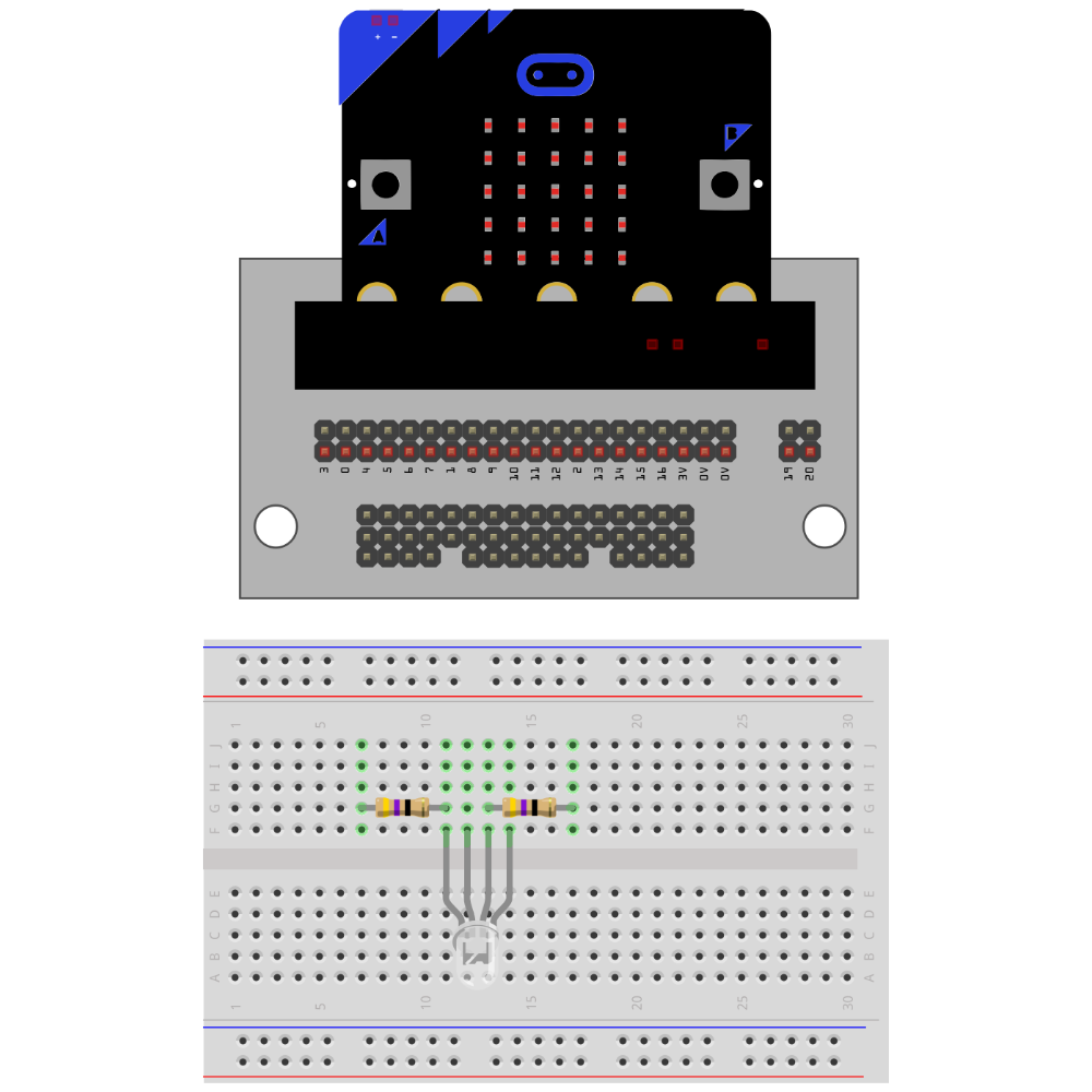
This circuit should be similar to the circuit displayed below:

Predict and Explain#
Now that you have built your circuit, predict how electricity will flow through it using the RGB Color Code Model (255, 0, 0) or (0, 255, 0). Trace the flow of electricity through this system. Do you think the voltage changes using a different code, like (150, 100, 50)? How would a change in voltage affect the current flowing through the circuit, and what impact would this have on the LEDs? If you changed resistors, how would their values impact the voltage and current for each LED color?